

Wood panel structure
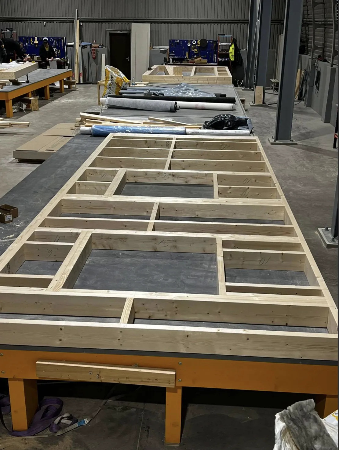
Prefabricated wall, floor and roof panels, factory-assembled to a fixed build-up and delivered ready to erect.
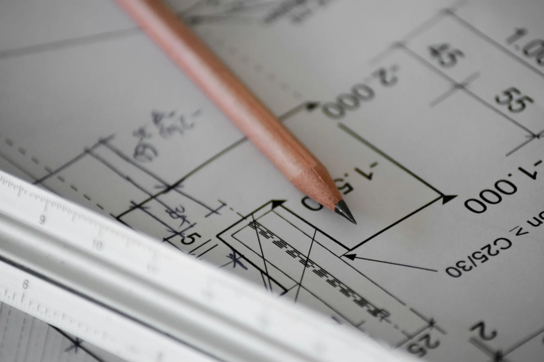

Architectural solution, structural statics, panel structure, thermal performance, acoustics, fire safety (REI30/60/90), moisture protection and building-services integration.
Sigulda factory, C24 Latvian timber, up to 1,500 m² produced per month on our own production line.
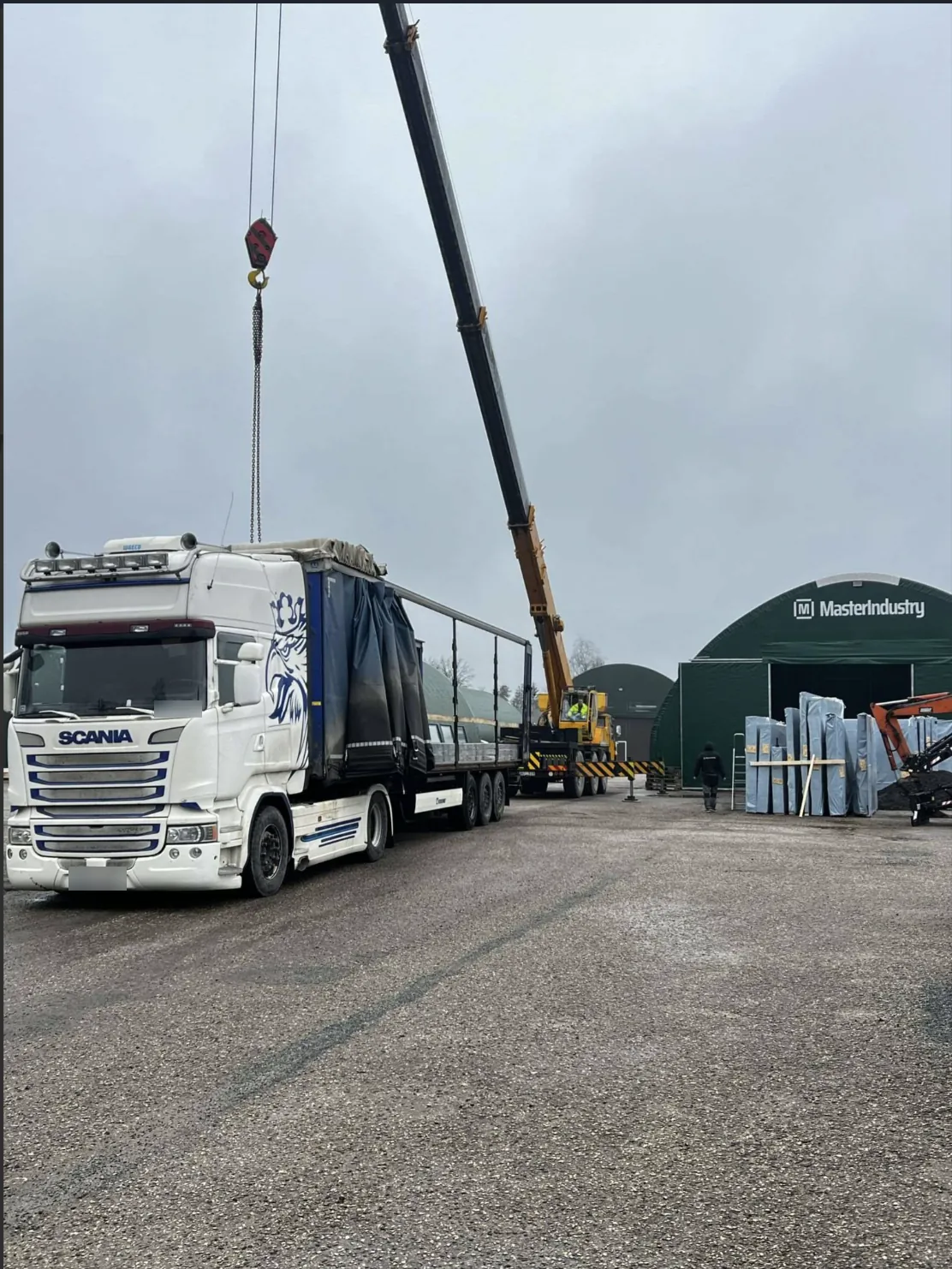
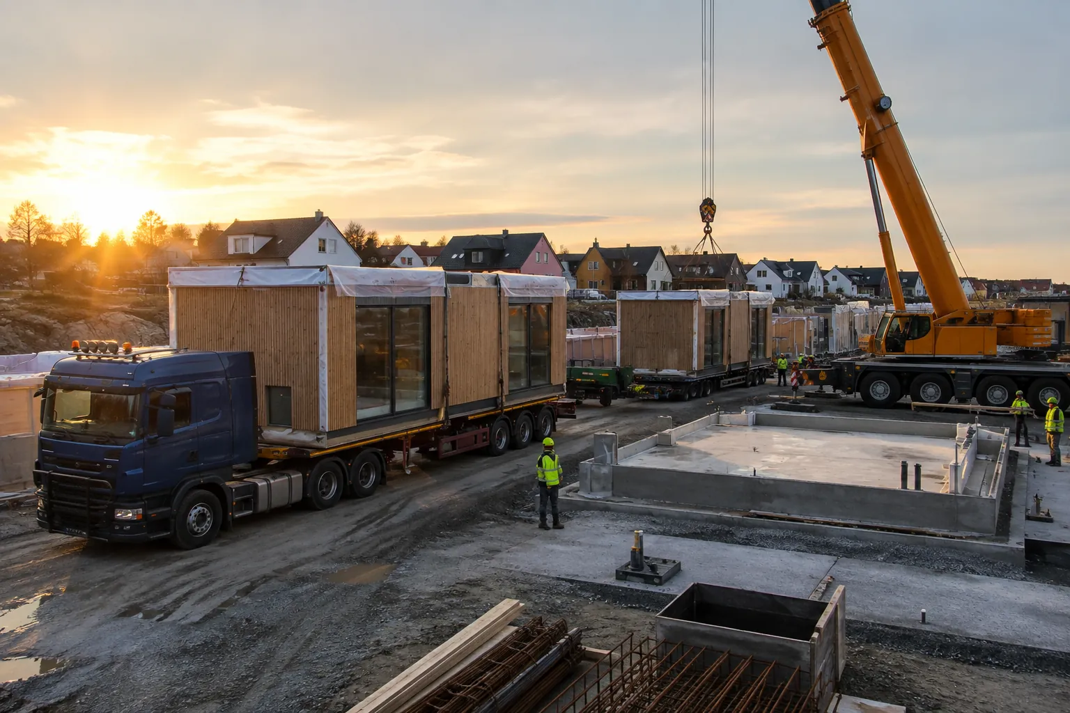
Packed to a loading plan with optimised cargo geometry for transport to Sweden, Norway and Switzerland. Roughly 40 to 50 m² of building area travels on one truck, auxiliary materials included, and every delivery is verifiable truck by truck.
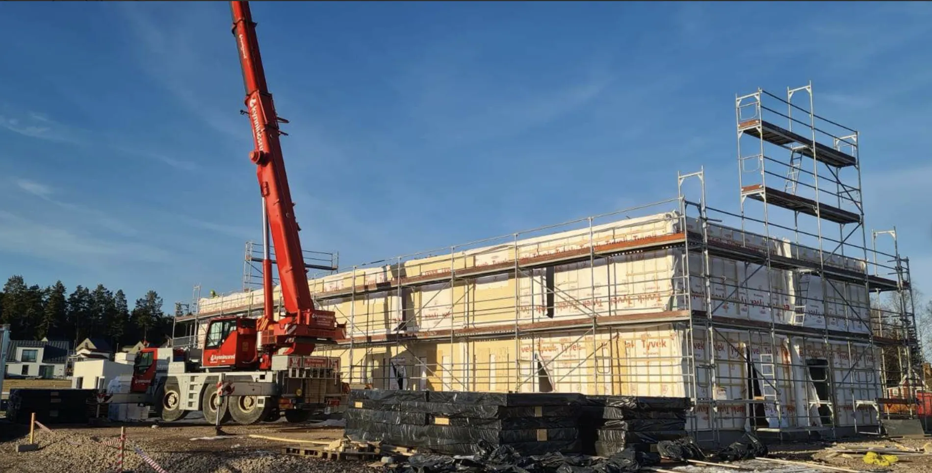
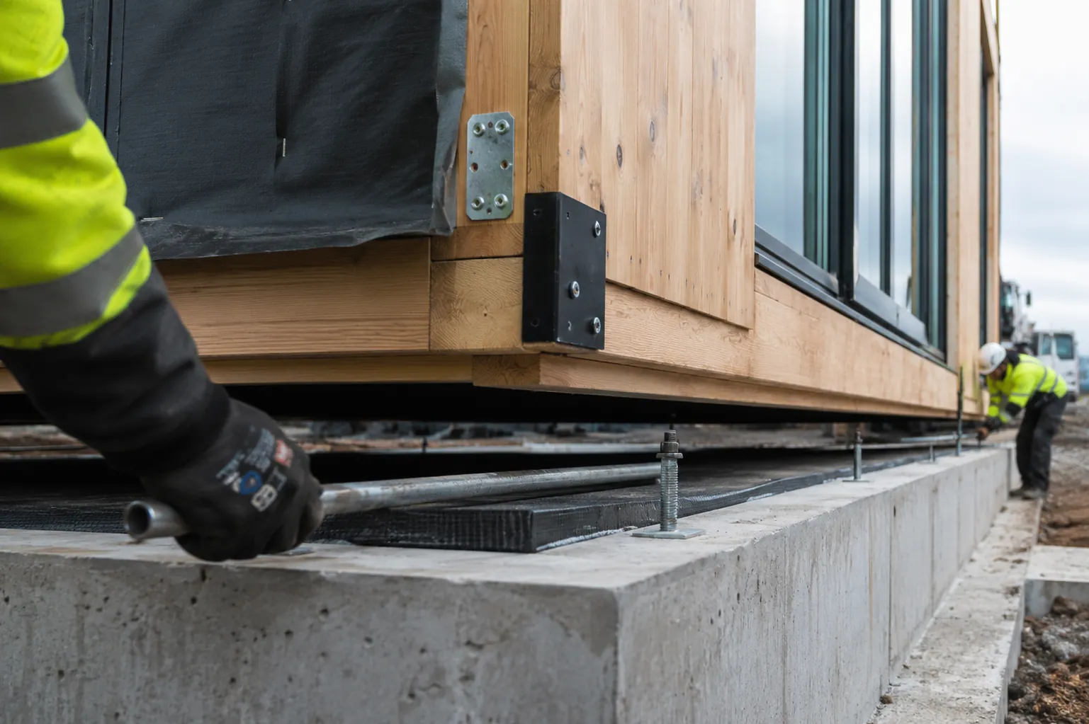
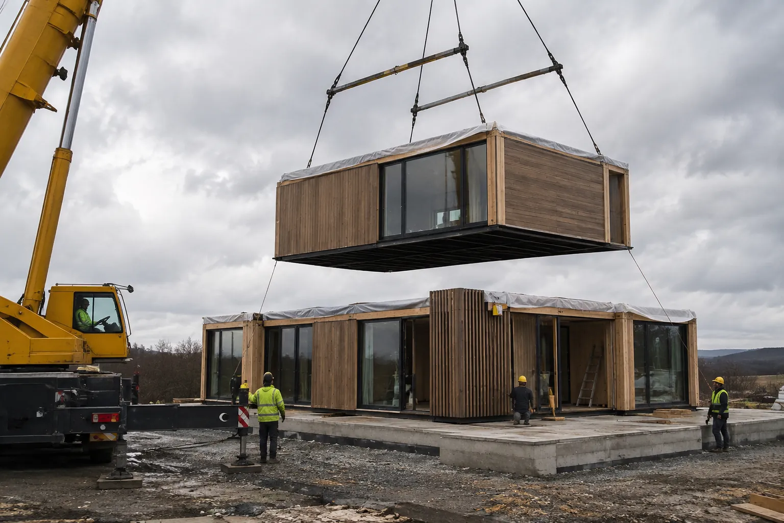
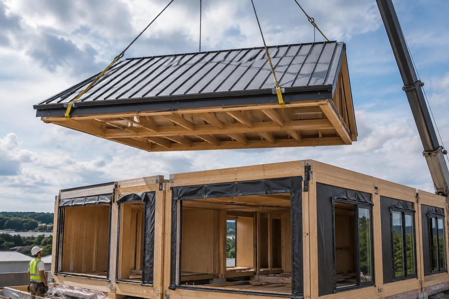
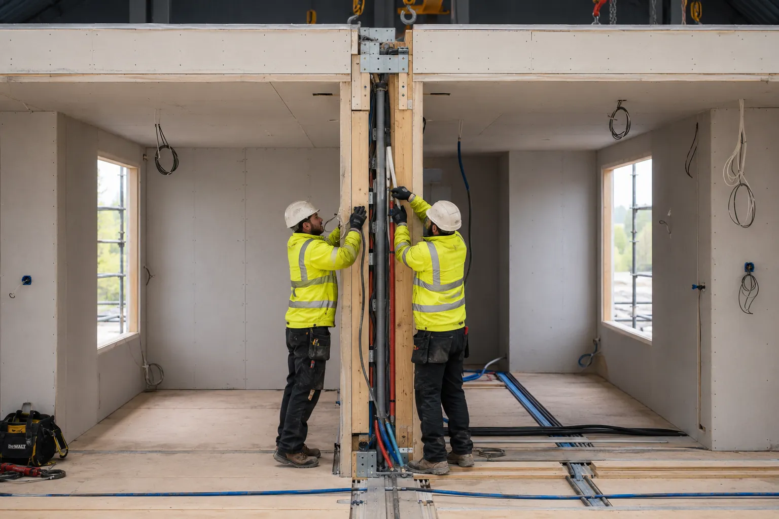
Assembled on site by MasterIndustry's own crews, never subcontracted. Work happens under roof cover, protected from the weather, with elements sealed and blower-door airtightness tests completed.
Airtightness tested (blower door) as standard, handed over with complete as-built documentation.
The scope form for Svartgarn. Every project gets its own.
Source: Form MI_1, Scope of Construction Activities, Rev. 1, 15 May 2026. Scope is set per project.
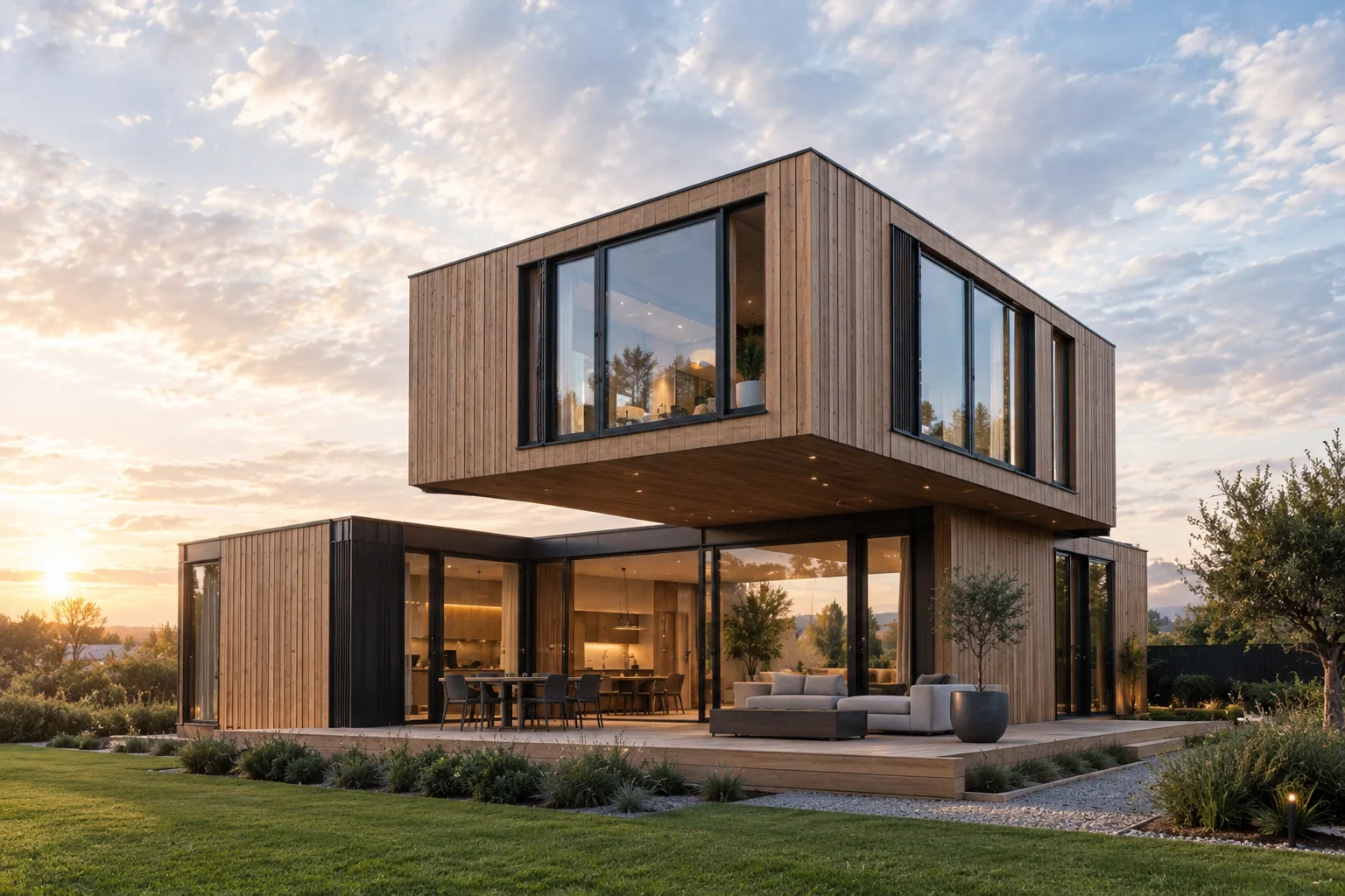
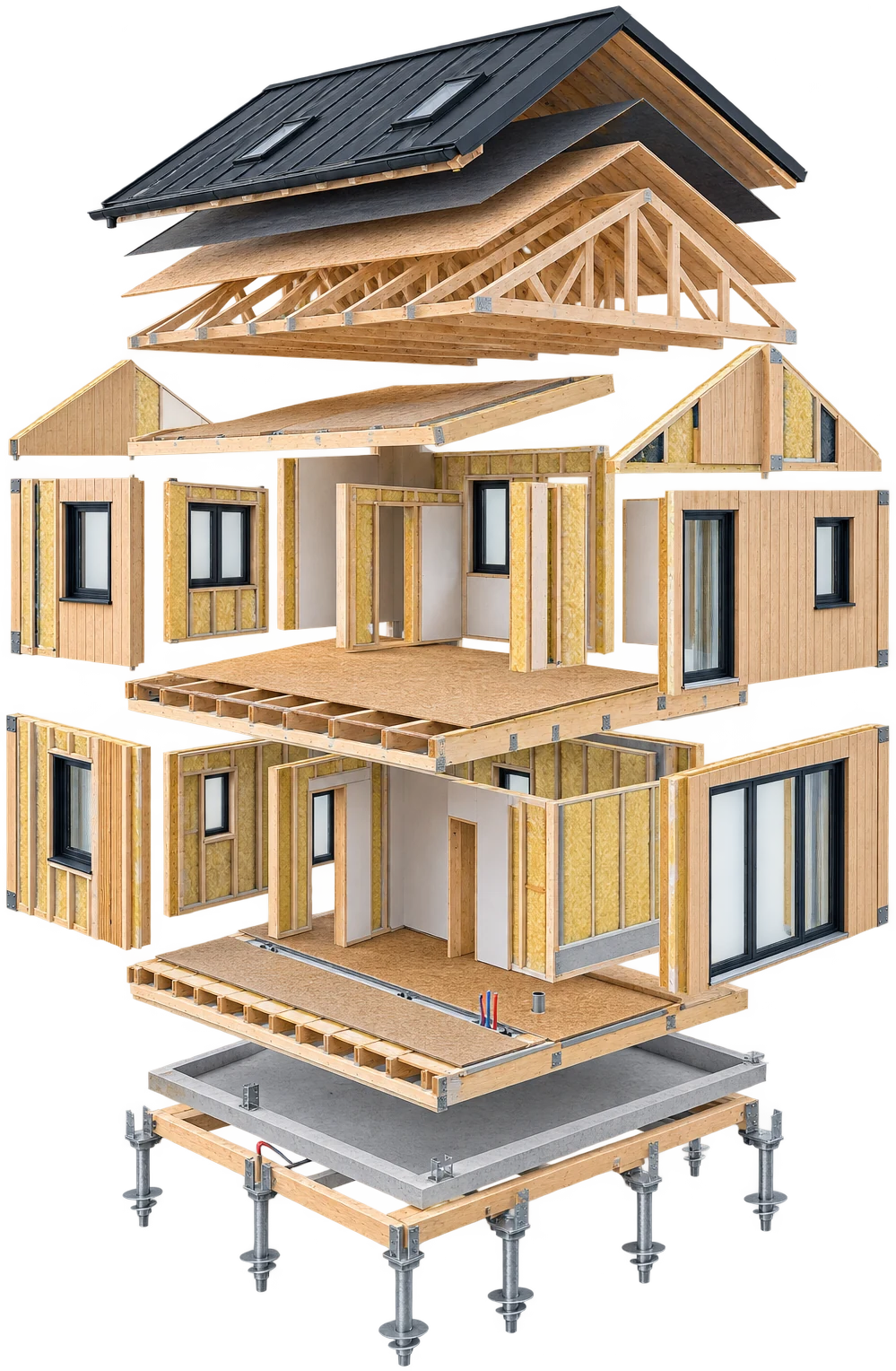 Illustrative render
Wall, floor and roof panels are assembled in the factory, numbered and packed for sequenced assembly on site.
Prefabricated wall, floor and roof panels, built to a fixed build-up and delivered ready to erect.
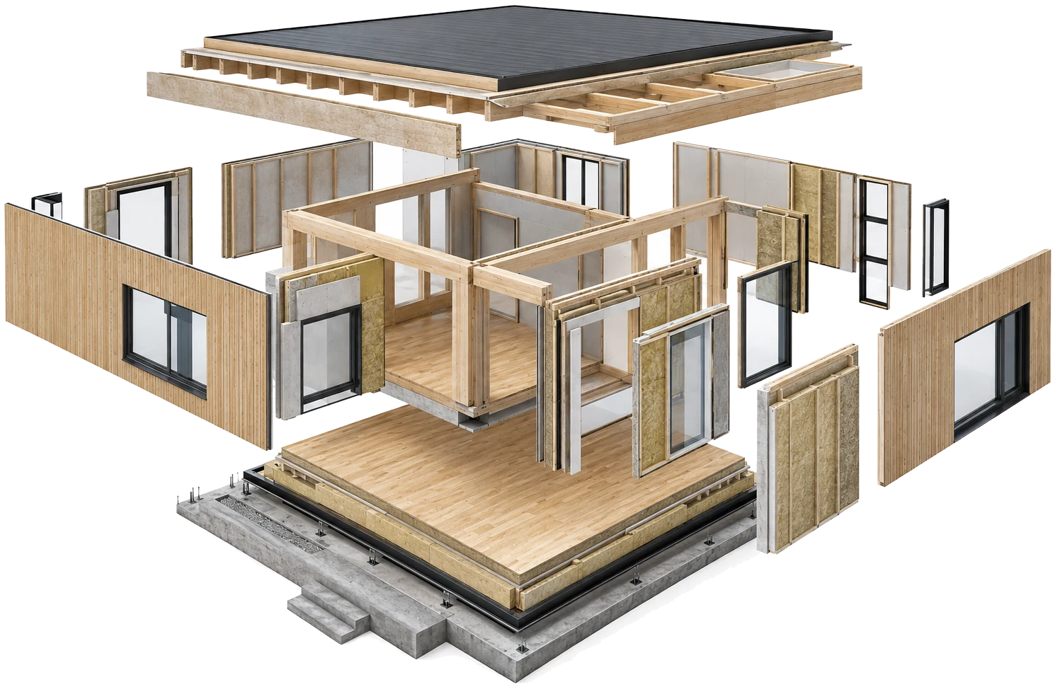
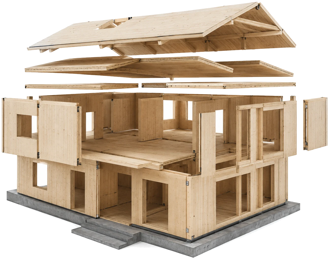
GL24h glulam and cross-laminated panels where the design needs long spans or stiff diaphragms.
Every element is numbered and packed to a loading plan, then lifted into sequence by our crews.
Prefabricated wall, floor and roof panels, factory-assembled to a fixed build-up and delivered ready to erect.
Structural glulam, GL24h grade, for long spans and exposed frame structures.
CLT panels for floors, walls and roof diaphragms that need high dimensional stability. Floor panels run to 220 mm.
Plywood sheets combined with the panel, glulam and CLT structure, on a monolithic concrete foundation with elevator shafts.
Wood panel and cross-laminated timber, shown layer by layer.
Sequesters carbon for the structure's lifespan instead of releasing it in production.
Timber is light for its strength, which keeps the building light and foundation loads down.
Panels are produced in a controlled factory while site works proceed in parallel.
Insulated panel build-ups are engineered per project using Ubakus hygrothermal modelling.
Layered assemblies are specified to meet party-wall and floor acoustic requirements.
Fire ratings of REI30, REI60 or REI90 are engineered to the specific building.
Vapour barrier and breather membrane layers are specified, then tested before handover.
Panel systems adapt from single modular units to multi-apartment developments.
Bar length shows relative panel depth
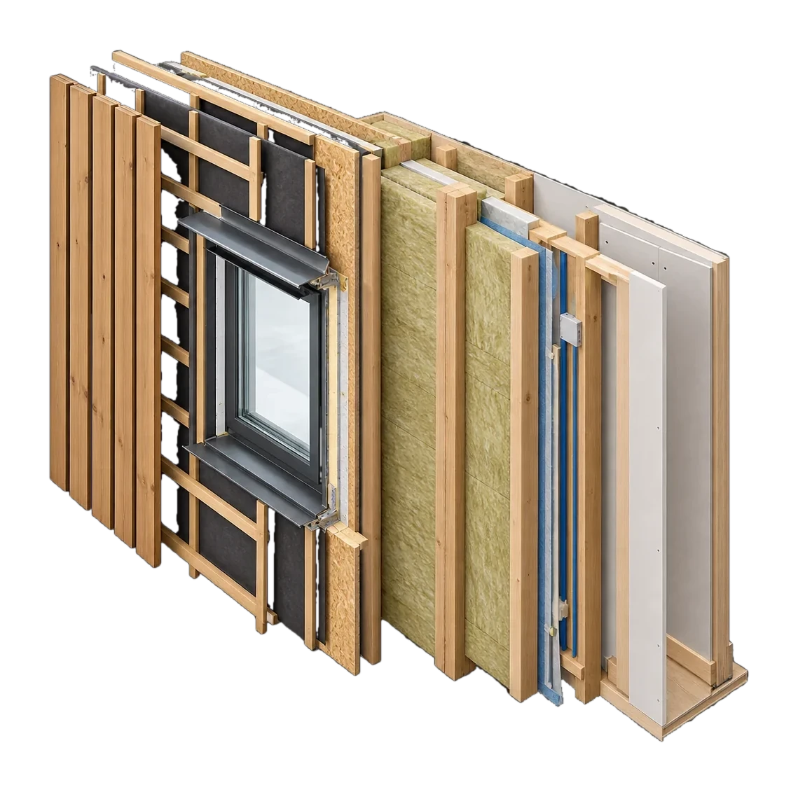
Calculated values from our assembly sheets. Choose an assembly to see every layer and its thermal data.
Schematic section. Thickness to scale, length not to scale.
33% below the 0.24 reference limit for existing buildings printed on the sheet (GEG 2020/24).
Used on Svartgarn.
Schematic section. Thickness to scale, length not to scale.
Between two heated rooms. The sheet lists no thermal requirement.
Used on Svartgarn.
Schematic section. Thickness to scale, length not to scale.
Between two heated rooms. The sheet lists no thermal requirement.
Schematic section. Thickness to scale, length not to scale.
Between two heated rooms. The sheet lists no thermal requirement.
Schematic section. Thickness to scale, length not to scale.
Between two heated rooms. The sheet lists no thermal requirement.
Schematic section. Thickness to scale, length not to scale.
54% below the 0.24 reference limit for existing buildings printed on the sheet (GEG 2020/24).
Schematic section. Thickness to scale, length not to scale.
42% below the 0.24 reference limit for existing buildings printed on the sheet (GEG 2020/24).
Schematic section. Thickness to scale, length not to scale.
Off the scale: no insulation layer in this build-up.
This build-up has no insulation layer. Thermal protection comes from the ceiling below it.
U-value in W/(m²K). Lower is better.
Values are calculated, not measured, and are taken from each assembly sheet. Wall, ceiling and balcony sheets use inside air at 20 °C and 50 % humidity; rooms between two heated spaces carry no thermal requirement on the sheet. Full assembly sheets are issued on request.
Request the assembly sheetsOur crews set elements under roof cover. Each step below is an illustrative render.
Life-cycle assessment per project to quantify embodied and operational impact.
Environmental Product Declarations in progress for core panel systems. See the certification roadmap.
Production-engineering software that turns structural design directly into factory cutting lists.
Hygrothermal modelling for U-values and condensation risk in every wall build-up.
Passive House methodology available on request for qualifying projects.
A carbon-reduction strategy across material sourcing and production. Target dates are on the roadmap.
Full engineering reports (Ubakus outputs, LCA data, SEMA production files) are issued on request.
Request the engineering pack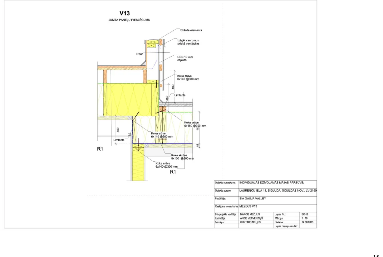
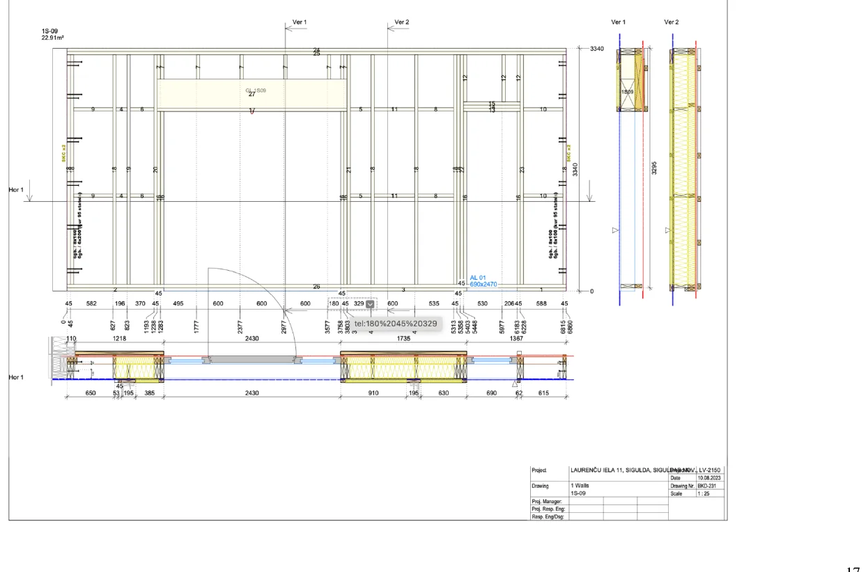
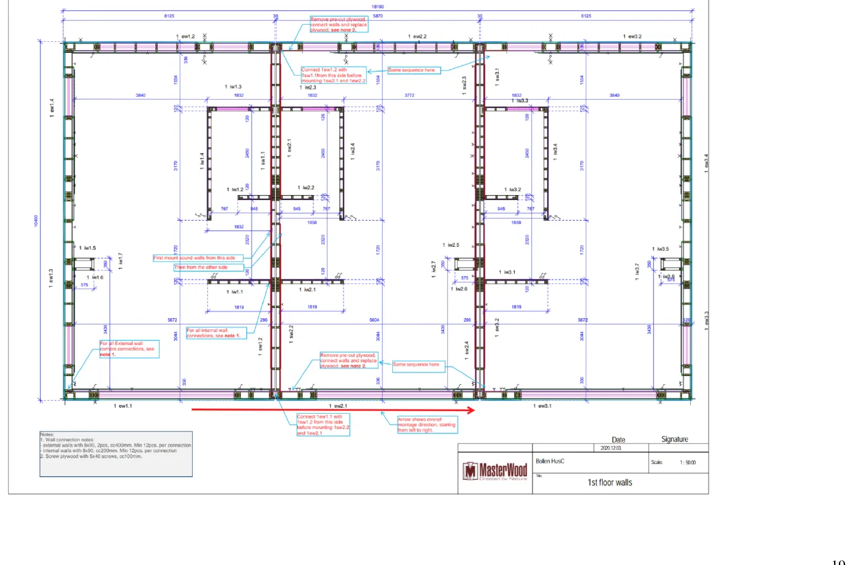
Optional on request: CO2-zero calculation, energy certification and LCA. Full drawing sets are issued per project.
Ask for a sample setWe reply with a realistic lead time, not a sales call.